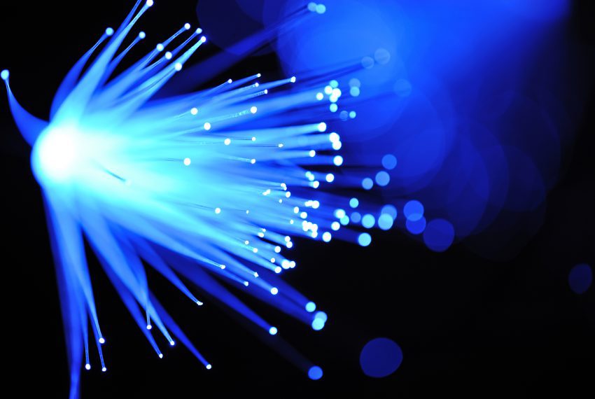
The other constructions include plastic optical fibre and plastic clad optical fibre. This section refers to all-silica optical fibre systems only.
In the simplest terms, optical fibre transmission is a series of pulses of light representing the 1s & 0s of binary encoding. The optical fibre guides and contains the light ensuring it travels from the transmitter to the receiver. As with copper infrastructure cabling systems, the portfolio consists of cable and connecting hardware of different categories and classes.
Fibre optic systems have the benefit over copper with respect to the maximum achievable distance. For a standards compliant installation, copper is generally limited to a maximum of a 100m channel, whereas fibre may support some applications for many kilometres. For this reason, fibre optics have traditionally been used in the backbone – typically linking telecommunications rooms – and copper is traditionally used for the horizontal. The backbone encompasses links between buildings. Cables that link buildings have additional challenges. If there is any metallic component, either the conductor medium or any part of the construction, then earth bonding has to be considered. Fibre optic cables are offered with an all dielectric construction, meaning total non-conductivity. This mitigates the need for earth bonding and any over-volt protection requirement. Additionally, as the physical size of the fibre cores are so small (the constructions are discussed later) the resulting strength members, yarns, water blockers etc. are reduced in size compared with the equivalent copper cable.
The backbone is not the exclusive use of fibre optic cabling. Customers are deploying fibre in the horizontal element of the infrastructure; sometimes referred to as Fibre To The Desk (FTTd).
Multimode & Singlemode
Fibre optic cabling can be split into two families – Multimode and Singlemode. ‘Mode’ means path, so the light travels down multi and single paths respectively.
Multimode can use the less expensive LED and VCSEL light sources to transmit the signal. This is referred to as ‘overfilled’ as the source is broad and floods the modes (and some of the cladding, hence overfilled). The core is manufactured with a graded index. This means that the central light path is ‘slower’ than the outer paths, which drastically reduces modal dispersion which is one of the limiting factors for the performance of multimode.
Singlemode requires a laser to transmit the signal along a single path. Lasers offer a high powered signal that can be transmitted for greater distances. However, the active equipment is a higher price than that of multimode.
The fibre core comprises of a core and a cladding. This cladding is then covered by a primary coating.The core is the medium that the light is transmitted along. The cladding is part of the manufacture of the glass. Typically, the cladding is of a consistent size for multimode and singlemode; namely 125µm. Likewise, the primary coating is usually 250µm for both multimode and singlemode. The primary coating can be coloured to differentiate between the cores within a cable.
Terminating connectors
The termination of the connectors on the end of the fibre can be achieved by either splicing a pigtail to the end or by directly installing a connector. Direct installing of the connector involves preparing the fibre to bare the cladding. This is then fixed into the ferrule with adhesive. The adhesive used takes many forms, including hot melt, cold cure and hot cure to name a few. The end face is then polished and inspected until the desired standard is achieved. This is a very labour intensive method relying on the skill of the installer. It also puts a larger demand on the installer to maintain consistency.
Although Digitech can provide this service we more often use the fusion splice method where a manufactured pigtail is fusion spliced onto the fibre. The pigtail is a 1-2m length of fibre with the desired connector pre-attached. As these are factory made, the quality of the termination and consistency can be assured and maintained. The fusion splicer then joins the end of the pigtail and the fibre cable together using an electrical spark. The splice is covered with a heat shrink splice protector. Our fusion splicer aligns the fibre cores and splices automatically. This ensures consistency and a high quality through the whole installation. A Digitech engineer, in ideal conditions, can perform in excess of 80 fusion splices in a day, including preparation of the cable and final mounting in the patch panel.
Diverse routing
The fibre optic network is often used in the backbone and data centres. In both these instances the network plays a critical part of the business. It is for this reason that a level of redundancy should be designed into the network design. Effectively, a risk assessment needs to be carried out before designing the network. This risk assessment should include what the risk is to the business if the network fails (this will highlight the level of importance and investment that is prepared to be committed to the network). Complementing this, the physical risks need to be assessed. Whether it is a single fibre core breakage, connecting equipment failure or the proverbial JCB digging up a buried cable, these are all physical risks. The risks can then be mitigated to some extent with Diversity, Redundancy and Capacity. Physical diversity is achieved by connecting the hardware with two or more different connections. The routing of these diverse links needs to be planned so that they do not follow the same route or share the same containment. That way, if there is a breakage in one link the other may be used. Networking equipment is often supplied that has two or more connections and can be configured to automatically switch routing. Although the active equipment may use all of the diverse routing in normal operation, the network is designed such that this offers the levels of redundancy should sections of the physical networks be compromised. The level of redundancy required should be identified in the risk assessment. As the traffic levels and demands increase on the network, a good design will allow capacity to accommodate this. In short, “Design for Tomorrow not Today”.
Termination & Installation of Fibre Optic
Digitech are able to offer a nationwide fibre optic installation and termination service of OS1 & OS2 Singlemode and OM3, OM4, OM5 Multimode fibre optics. Installations are carried out in all environments from office spaces and building risers to heavy industrial factories and manufacturing plants. The installations are carried out utillising containment including basket and tray work together with inter building underground ducts. The fibre optics range from 4 to 96 cores internal/external loose tube (LT) and tight buffered (TB) construction through to corrugated steel tape and steel wire armoured for more demanding environments.

